Transformer equivalent circuit in phasor form Transformer equivalent winding qph quoracdn resistance Transformer diagram and constructional parts
Ideal Transformer - Electrical Technology
Transformer wye phasor connections wiring diagrams connection relay electricalacademia
Ideal equations losses
Transformer wiring diagram control 480 power phase 120 volt motor circuit circuits single diagrams 480v electrical acme secondary transformers 120vTransformer phase motor primary circuits starter 120v kva Diagram supply power voltage circuit wiring transformer resistive less reducer golf cart transformerless lowIdeal transformer in detail with schematics and equations.
Equivalent circuit diagram of single phase transformerTransformer working principle Pulse transformer operating principlesCircuit output amplifier transformer power diagram seekic analog basic.
![TransformerLess Power Supply](https://i2.wp.com/electrosome.com/wp-content/uploads/2012/12/Resistive-Transformer-Less-Power-Supply-Circuit-Diagram.jpg)
Three phase transformer connections
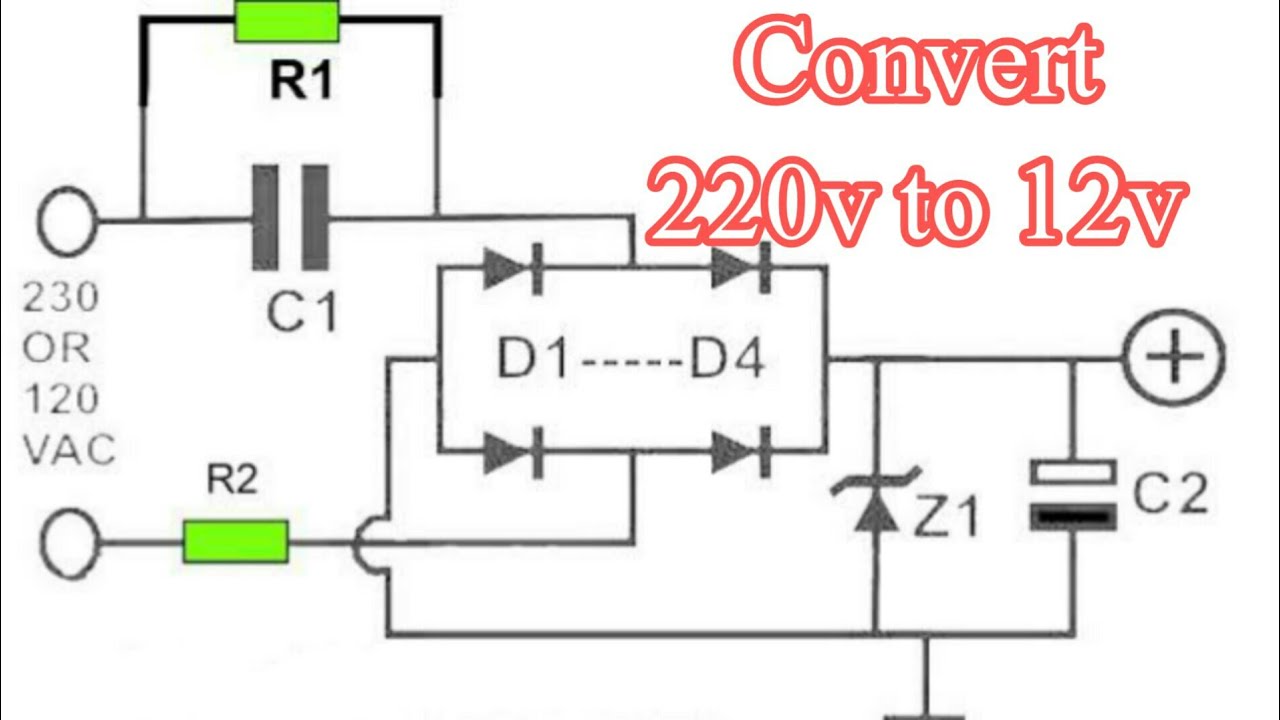
Transformer circuit working principle works electrical gif fig each electricalacademiaTransformer equivalent phasor referred voltage equations determination apk electricalacademia induced Square d single phase transformer wiring diagram220v ac to 12v dc converter circuit diagram 12v transformer less power.
Wiring of control power transformer for motor control circuitsDiagram transformer wiring transformers circuit primary electric secondary coil step voltage core down iron simple basic utexas farside lectures ph Transformerless power supplyPulse transformer gowanda.
![Transformer Equivalent Circuit in Phasor Form | Electrical Academia](https://i2.wp.com/electricalacademia.com/wp-content/uploads/2017/10/Transformer-Equivalent-Circuit-in-Phasor-Form-4.gif)
Transformer arises impedance emf
Potential current electricalacademiaTransformer output power amplifier circuit diagram Difference between current transformer and potential transformer12v dc circuit ac diagram converter 220v transformer power supply less.
.
![Square D Single Phase Transformer Wiring Diagram - Wiring Diagram](https://i2.wp.com/electrical-engineering-portal.com/wp-content/uploads/2016/10/control-transformer-wiring-diagram.png)
![Transformer Output Power Amplifier Circuit Diagram - Analog_Circuit](https://i2.wp.com/www.seekic.com/uploadfile/ic-circuit/s20113162455458.gif)
![Three Phase Transformer Connections | Electrical Academia](https://i2.wp.com/electricalacademia.com/wp-content/uploads/2017/12/Delta-Wye-Three-Phase-Transformer-Phasor-Diagram-1.gif)
![Equivalent Circuit diagram of single phase Transformer](https://i2.wp.com/www.electricalunits.com/Image/Transformer/EquivalentCir.png)
![Ideal Transformer - Electrical Technology](https://i2.wp.com/www.electricaltechnology.org/wp-content/uploads/2012/11/Ideal-Transformer.png)
![Ideal Transformer in detail with Schematics and equations](https://i2.wp.com/www.electricalclassroom.com/wp-content/uploads/2020/09/Ideal-transformer.png)
![Ideal transformer circuit diagram | Download Scientific Diagram](https://i2.wp.com/www.researchgate.net/profile/Suresh-Daram/publication/224937629/figure/download/fig1/AS:302889265319944@1449225836678/Ideal-transformer-circuit-diagram.png)
![220v ac to 12v dc converter circuit diagram 12v transformer less power](https://i.ytimg.com/vi/H8dDBk4qL-E/maxresdefault.jpg)
![Wiring of control power transformer for motor control circuits | EEP](https://i2.wp.com/electrical-engineering-portal.com/wp-content/uploads/2016/10/control-transformer-control-circuit.png)
![Transformers](https://i2.wp.com/farside.ph.utexas.edu/teaching/316/lectures/img1136.png)